Phase 1
Design Process
Product Definition & Research
- Definition & PRD
- Quote
- Market Research & BOM
- Industry Styles and Trends
The design process starts by defining the problem and setting the requirements. We discuss the features, schedule, and budget, then provide a quote.
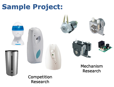
After the quote is approved, we research the industry and competitors while getting up to speed on any underlying technology.
We end with a rough overview of all the parts needed and feature set.


Phase 2
Design Process
Concept Sketches
- Blue sky brainstorming of aesthetics and mechanisms
- Sketches for different design directions
- Review and approval
- Refinement & concept selection
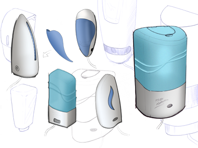
Concept generation starts with a rough sketch underlay. Dozens of concepts are developed in a rapid brainstorming session that allows us to discover multiple directions and possible design languages.
The favorites are then translated into workable concepts while trying to keep the spirit of the design intact. The designs are then reduced to 2-3 hybrids and refined in a second round of sketching and presentation. The chosen design is then refined further to create the final concept.
Phase 3
Design Process
CAD Modeling & Appearance Model
- Take sketch concept in to CAD
- Shaping and adding features
- Appearance model
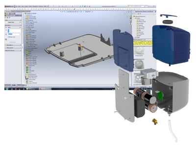
The Final concept sketch is modeled in Creo or SolidWorks through parametric modeling. Features are added one at a time and given dimensions and constraints that allow the model to update automatically when changes are made in the future.
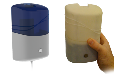
Once the CAD model is developed, the file can be used to create realistic renderings, 2D Patent Drawings, and exported as an STL file for rapid prototyping.
Phase 4
Design Process
Design for Manufacture
- Identify custom parts and create BOM
- Design each custom part in CAD
- Source vendors and OEM parts
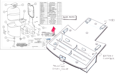
The design is then detailed for the manufacturing process (D.F.M.). It is given wall thickness, draft angles, mounting bosses, and supports. Additional parts such as buttons or battery doors are modeled as separate files and added to the assembly. The full assembly can then be moved around and assembled in the computer to make sure all the parts fit together properly.
Phase 5
Design Process
Working Prototype
- Part creation & assembly
- Testing
- Last minute updates
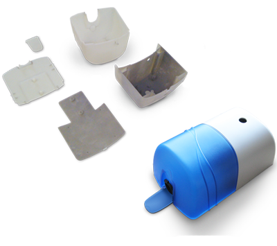
A second prototype is made of all the individual parts as they would be mass produced. The Product is assembled with working components and the design is tested. Feedback is gathered from the testing and the CAD file is updated. Additional rounds of testing ensure better quality for manufacturing. Common testing rounds include: Usability, Manufacturability, and Safety.
Phase 6
Design Process
Manufacturing Support
- 2D Drawings
- Tooling Quotes
- Hand-off
- Ongoing Support
After the prototype is assembled and validated, 2D drawings will be developed from the CAD files that detail the requirements.
The drawings are sent to manufacturers to get quotes. There are many options including full turn-key offshore outfits to local specialists who can assemble, test, and ship the final units.
This is also the time for last minute changes. Sometimes a tooling expert will recommend modifying a component to save money or decrease complexity. Large changes will require further prototypes.